![]()
Double Ferrule Fittings - Overview
Fluid Controls Double Ferrule Compression Tube Fittings provide leak proof torque free seals at all tubing connections. They eliminate hazardous leaks in instrumentation, process, pneumatic, hydraulic, gas and other applicable tubing system which could otherwise turn out to be costly to the installation.
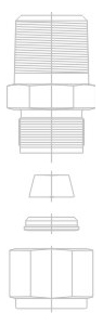
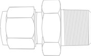
The basic Fluid Controls Double Ferrule Tube Fittings is a four piece Fitting consisting of the Nut, the Back Ferrule, the Front Ferrule and the Body. When installed, it becomes a five piece connection with the addition of the tubing providing a solid leak free joint.
The two ferrules grasp tightly around the tube with no damage to the tube wall. Exhaustive tests have proven that the tubing will yield before a Fluid Control Double Ferrule joint starts leaking.
The secret behind the success of the Fluid Controls Double Ferrule Fittings lies in the two ferrule design which is a combination of geometry and metallurgy. All the action in the fitting is by an axial movement along the tube instead of a rotary motion to create the joint. This axial movement prevents any torque to be transmitted from a fitting to the tubing. Since there is no initial strain in the tubing, the making of the joint does not weaken the tubing.
Another advantage of the Fluid Controls Double Ferrule Fittings is that the sequential action of the twin ferrule overcomes variations in the wall thickness, hardness and dimensional tolerance of the tubes. This way proper ferrule interaction compensates for most of the variables which lead to failure in other fittings.
Fluid Controls Double Ferrule Fittings are easy to install and require no special tools in the process. They are reusable several times and can withstand heavy impulse and vibration both in vacuum and pressure systems. Absence of damage to the tube surface prevents fatigue failure.
Fluid Controls Double Ferrule Compression Tube Fittings Have The Following Features
SERVICE
- Fluid Controls Double Ferrule Tube Fittings are available in a wide range of materials, sizes, connections and configurations from our local distributors with substantial back up stocks to support our dealers inventories.
TUBING SELECTION
Proper selection , handling, installation of tubing when combined with the proportion of the Fluid Controls Double Ferrule Tube fittings are essential to reliable tubing systems. Although, Fluid Controls Pvt. Ltd. is not a tubing manufacturer or supplier, we feel it is our duty to impress on our customers the vital importance of careful selection of high quality tubing in order to install safe and leak free systems. Fluid Controls will be happy to assist in the selection of such tubes to our customers when requested.
Selection of tubes are based on the material, hardness, wall thickness and surface finish. The ASTM specifications for various tubes cover material, hardness and wall thickness. They do not give details on the surface finish.
For example, ASTM A 269, one of the most widely used specifications reads as follows in clause 14.1 under the title “FINISH”.
” Finished tubes shall be reasonably straight and have smooth ends free from burrs. They shall be free from injurious defects and shall have a workman like finish. Minor defects may be removed by grinding provided the wall thickness is not decreased to less than that permitted in clause 13″.
The ASTM is silent on the surface finish which is required to be smooth and free from any scratches, axial or circumferential which will allow leakage paths along the joints.
We give our comments below on the selections of tubes. These requirements are specified under section 3.1.9 of ASTM A 269 or section 3.1.11 of ASTM A 213
TUBING HARDNESS
Tubing must always be softer than the fitting material by using the suggested hardness of the tubes as explained in tubing specification you will ensure joints which work perfectly.
The most misunderstanding about tubing hardness are in the area of stainless steel tubing. Fluid Controls Double Ferrule Tube Fittings made from stainless steel have been tested successfully with tubing hardness upto RB 90, the maximum hardness allowable under ASTM A 213 and A 269. Although such tubing hardness is permissible and Fluid Controls Double Ferrule Fittings will perform satisfactorily on such tubing, they will not give the maximum advantage and performance for tubes of hardness above RB 80. Hence, it is suggested that when purchasing stainless steel tubes to ASTM A 213 / A 269, you specify that the hardness of the tubes should not exceed RB 80. Better still we have found that the best results are obtained where the stainless steel tubing hardness is in the range RB 70-74. Such tubing ( RB 70-74) lowers installed costs because it is more easily bent and installed.
Tubing installers should be particularly careful that the full suggested one and quarter turns after snug tight be performed to ensure the proper joints. This will give the best performance This is especially so in the case of harder tubing where higher torques are required.
We again repeat that the RB 80 maximum hardness is a suggestion and not a restriction against the use of Fluid Controls Double Ferrule Fitting in stainless steel to increase the performance of the fitting. However, if the tubing hardness exceeds RB 90, special fittings needs to be ordered.
TUBING WALL THICKNESS
The allowable pressure rating of tubings for the wide range of wall thickness are calculated from “S”values as specified by ANSI Code B 31.1. The range of tubing wall thicknesses vary from 0.028 ” to 0.109 ” in the inch OD series and 0.75 mm to 2.5 mm in the Metric OD series respectively. These wall thicknesses are generally preferred for tube sizes upto 1″ OD and 25mm OD in the two systems respectively. For higher tube sizes, these wall thicknesses may be increased to 0.125 or ( 3mm) and 0.167 ” or( 4mm )in the inch (metric) system respectively.
Tubings with higher wall thickness are generally not recommended as they may lead to lowering of performance and higher torque requirements to create the joint. Tubings with lower wall thicknesses are also not recommended as there is a possibility of collapse of the tube.
Fluid Controls will be very happy to provide their customers with working pressure ratings as per ANSI Code B31.1 for various wall thicknesses in the above mentioned ranges for inch and metric size tubings.
TUBING FOR GAS SERVICE
For the greatest safety factor against surface defects in any gas system it is recommended that the wall thickness employed be not less than that shown in the table below;
| Tube O.D | Suggested Minimum Wall Thickness | Tube O.D | Suggested Minimum Wall Thickness |
| 1/16" | .028" | 3/4" | .062" |
| 1/8" | .028" | 7/8"(20mm) | .073" |
| 1/4"(6mm) | .028" | 1"(25mm) | .083" |
| 5/16"(8mm) | .035" | 1-1/4" | .104" |
| 3/8"(10mm) | .035" | 1-1/2" | .125" |
| 1/2"(12mm) | .041" | 2" | .167" |
| 5/8"(16mm) | .052" | - | - |
Light gases such as helium, hydrogen, nitrogen, etc have very small molecules which can escape through even the minutest leak path created by surface defect on the tubing. As the tube OD increases, so does the likelihood of a scratch or other surface defect interfering with proper sealing.
The most successful connection for gas service will occur if all the installation instructions are carefully followed and the heavier permissible wall thickness of tubing are selected. A heavy wall thickness resist ferrule action more than a thin wall thickness allowing the ferrules to coin out minor surface in perfection. A thin wall tube will collapse offering little resistance to ferrule action during preparation of joints. This reduces the chances of coining out surface defects essential for gas service.
TUBING HANDLING
Scratches on tube OD are a potential source of problems in leak-tight tubing systems. Good handling practices can greatly reduce scratches and protect the good surface finish of well made tubes.
Tubing should never be dragged out of a tubing rack. Particularly in sizes ¾” and larger, the weight of the length being pulled out is sufficient to gouge the OD if there are any burrs on the end of the tubes below it in the rack.
Tubing should never be dragged across cement, asphalt, gravel or any other surface which could scratch the surface and recreate the leakage parts.
Tube cutters or hacksaws should always be sharp, and you should not try to take too deep a cut with each turn of the cutter or with each back and forth motion of the saw blade.
Tube ends should always be debarred. This allows more easy entrance of the tube into the fitting bore and helps to assure the installer that the tubing will go all the way through the ferrules without damage to the ferrule sealing edge.
TUBING SELECTION
We give below the specifications to be followed for the various tubings for use with Fluid Controls Double Ferrule Compression Fittings.
CARBON STEELTUBING
Soft, annealed carbon steel hydraulic tubing to ASTM A 179, Din 2391 or equivalent based on ultimate tensile strength of 47000 psi and for metal temperatures not to exceed 20 deg C to 100 deg C. For higher temperature service, reducing factors for elevated temperature operation as specified in table 302.3 1A and 304.1.2 of the code for pressure piping in ANSI B31.3 should be applied..
The hardness of the tube is recommended to RB 72 or less.
The tubes should be suitable for bending and flaring and free of all surface defects and imperfections.
STAINLESS STEELTUBING
Annealed 304 or 316 Stainless Steel tubing to ASTM A 269 or A 213 or equivalent based on ultimate tensile strength of 75,000 psi and suitable for temperatures 20 deg C to 100 deg C.
The hardness of these tubes is not to exceed RB 80 and is preferred in the range RB 70-74.
Tubes to be suitable for bending and flaring and should be free of surface defects and imperfections.
COPPER TUBING
Annealed, soft, seamless copper tubing to ASTM B 75 or ASTM B 88 based on an ultimate tensile strength of 30,000 psi and for a temperature in the range of 20 deg C to 80 deg C. Maximum hardness of the tube not to exceed RB 50. Tubes preferred in the range RB 40-45.
MONEL 400 TUBING
Fully annealed Monel 400 seamless tubing conforming ASTM B165 or equivalent and based on ultimate tensile strength of 70,000 psi. and for use with temperatures 20 deg C to 90 deg C.
Hardness of the tube must be RB 75 maximum and is preferred in the range RB 68-72.
THREAD SPECIFICATIONS
Fluid Control connectors have one or more tubing end connections and the others with male or female pipe threads. There are a variety of pipe threads for which Fluid Controls Double Ferrule Fittings are available. The most popular thread connections are the American National Pipe thread (NPT) British Standard Pipe threads (BSP) and metric threads. These threads belong to standards of individual countries as well as ISO where they have been codified. All Fluid Control Fittings with pipe threads or stud end threads conforming to the specifications as detailed below.
- American National Pipe Thread (NPT) : Reference specification ANSI B1.20.1 : 1983
ISO Parallel Pipe Thread (British Standard Pipe Thread ) : Reference specifications BS 2779, ISO 228/1, DIN 259, JIS B 0202, IS 2643 - ISO Taper Pipe Thread (British Standard Pipe Taper Thread) Reference specification BS 21, ISO 7/1, DIN 2999, JIS B0203, IS 554
- Unified National Pipe Threads: Reference specifications ANCI B1.1 : 1964
TECHINCAL SPECIFICATIONS TO WHICH FITTINGS PERFORM
There are no standards available for Double Ferrule Compression fittings. The working pressure are restricted by the maximum working pressure of the tubes to be used with the fitting design is such that the tubes will burst before the breakage of the joint. Accordingly, the working pressure outlined in the section entitled ‘Allowable Pressure Ratings for Tubing will prevail as the working pressure for these fittings.
The maximum working pressure of these fittings is also restricted by the pressure ratings for the pipe end connections adopted (see section entitled ‘Pressure Ratings for Pipe Ends’ ). The lower of the two will be the maximum working pressure for the fittings.
There are no standard specifications available for type test requirement of Double Ferrule Compression Fittings. The attempt has been made by British Standards Institute to formulate a Standard BS 4368: Part IV 1984. A similar Standard has been formulated by the Indian Standards Institute vide IS 10103 : 1982. Both these Standards refer to Single Ferrule Fittings. They can however be adopted for Double Ferrule Fittings as well. The Standards cover the basic type test requirements for fittings assembled in a standard test assembly as outlined in the above Standards. The tests specified by these Standards are as follows:
PROOF PRESSURE TEST
Test assemblies to be subjected to a pressure of 1.5 times the maximum working pressure of the fittings applied at the rate of 200 kg/cm2 per minute and maintained at final pressure for five minutes with out leak.
DISMANTLING AND REASSEMBLY TEST
Test assemblies successfully completing the Proof Pressure Test above are dis-assembled and assembled twenty five times after which they must pass the Proof Pressure Test.
MINIMUM HYDRAULIC BURST PRESSURE
Apply hydraulic pressure to the test assembly upto a maximum of four times the working pressure at the rate not exceeding 200 kg/cm2 per minute and maintain for five minutes without leak.
MINIMUM STATIC VACUUM TEST
Test assemblies satisfactorily proof pressure tested are subjected to negative pressure upto 700 mbar and then isolated from the vacuum pump. The assembly must maintain the vacuum for fifteen minutes. The assemblies are suitably decreased before the test and total exhausted volume should not exceed 20% of the total assembly volume. This test can also be given at two temperature for cryogenic applications.
HYDRAULIC IMPULSE VIBRATION TEST
Test assemblies suitably proof pressure tested are connected to a hydraulic pressure impulse and vibration test bench and subjected simultaneously to Pressure Impulses at 30 to 100 cycles per minute and vibration in two mutually perpendicular planes at 1,300 to 2,820 cycles per minute for a minimum of 5 x 10⁶ pressure impulses and 20 x 105 vibration cycles. The method of choosing the displacement and the cycles is outlined in the Standards mentioned. The only permissible retightening is allowed after the first 1,000 pressure impluses to allow for bedding-in. When subjected to the test described this coupling should not leak in the assembly. Couplings that fail shall be examined for signs of cracking due to fatigue stress.
The above tests have been specified in the Standards BS 4368 Part IV :1984. Some customers working with high temperatures have specified a temperature cycling test which requires test assemblies to be subjected to suitable temperature cycles and then subjected to the Proof Pressure Test without leakage. Other customers working with gases have specified a helium leak test with leak rates not exceeding 2×10⁻⁶ STD. CC/SEC. Fluid Controls undertakes all these tests at their recognized laboratories to satisfy all customers technical requirements.
ASSEMBLY

FLUID CONTROLS TUBE FITTINGS come to you completely assembled, finger-tight. They are ready for immediate use. Dis-assembly before use can result in dirt or foreign material getting into the fitting and causing leaks.
FLUID CONTROLS TUBE FITTING are installed in three easy steps.
Step 1
Insert the tubing into the FLUID CONTROLS TUBE FITTING. Make sure that the tubing rests firmly on the shoulders of the fitting and that the nut is snug tight, in this position the tube does not rotate by hand.
Step 2
Before tightening the FLUID CONTROLS nut, scribe the nut at the 6.00 o’clock position.
Step 3
Now while holding the fitting body steady with a backup wrench, tighten the nut one-and-one quarter turns*
Watch the scribe mark, make one complete revolution and continue to the 9.00 o’clock position. *For 1/8″, 3/16″, 3 & 4 mm size tube fittings, only ¾ turns from finger-tight is necessary the joint is now complete.
HIGH PRESSURE APPLICATIONS, HIGH SAFETY FACTOR SYSTEMS
Due to the variation of tubing diameters, a common starting point is desirable. Therefore, use a wrench to snug up the nut until the tubing will not turn (by hand) in the fitting. Now tighten the nut one-and-one-quarter turns and the fitting is ready to hold pressure well above the working pressure of the tubing.
RE-TIGHTENING INSTRUCTIONS
Connections can be disconnected and re-tightened many, many times and the same reliable, leak-proof seal obtained every time the reconnection is made.
PRE-SWAGING
NOTE:-
Fluid Controls has a continuous and dynamic research and development program for the development of fittings in different materials, higher pressures and temperatures. The dimensions and information given in the catalog are subject to change without notice as a result of the findings in these programs.
